 The Prototype
Currently (January 2012) about three-quarters of the track is installed and working, slightly less than half of that has been detailed, but only a short test section has been painted. The decision to replace it all with ScaleSeven has not been taken lightly; neither has that work actually been started yet! All the electrics and the mechanical point-rodding were installed before the track was started so that it could all be tested. Below are some photos to show the progress even if most of the words (and there are lots of them planned!) are absent. Come back soon to check on me!
This page is currently a "work in progress" and I would not normally publish it in this condition. However the previous version had some HTML coding errors which has forced the premature release of this edition.
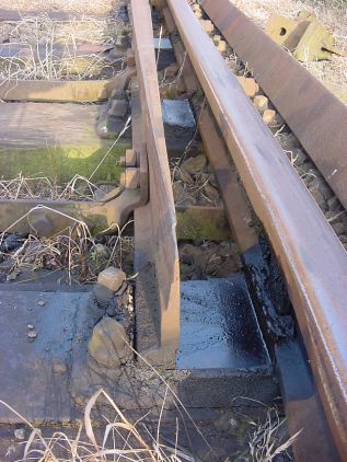
The PrototypeFor the period and location being modelled the track would have comprised rolled steel bullhead rail on cast iron chirs held with teak, oak or sprung steel keys mounted with bolts (GWR), spikes or screws onto wooden 10"x5" sleepers (plain track) or 12"x6" timbers (switches and crossings). That sentence covers about 100 years of engineering development.
Since then we've been upgraded in the UK to flatbottom rail fixed using clips to concrete bearers or slabs, although many locations still feature "heritage" infrastructure. When they become life-expired track components are often "cascaded" to less onerous duties. I think such a yard as Lumpy Sidings ought to have worn 85lb/yd rail with chairs to match. Unfortunately no manufacturer I've found makes rail and chairs of this size so I've had to use the slightly larger 95lb/yd equivalents.
TO DO: describe model components, links to c&l and exactoscale and templot and off the rails.
TO DO: Some text & pix here. descriptions of straight planing, semi-curved, curved planing; undercut etc switches; 1:20 inclination, terminology UK/USA switches/points/turnouts etc, table of planing lengths
The type of switch described below does not require joggles in the stock rails to accommodate it.
 1. Plane the back of the rail until the web is just broken into. The prototype only reduces the end of the web by a sixteenth of an inch so don't go too mad! However, the web of most model rail is overscale so you may wish to reduce it's thickness to a scale eleven-sixteenths of an inch to avoid the switch looking too "chunky". It is essential to be as accurate as possible with the planing length as a few thou can make a lot of difference to the switch angle.
 2. Put a set (that's a bend to you and me) in the rail at the planing length so that the end of the rail is aligned where the running face was (the picture should make this clearer). This location of this set is important since this affects the switch angle.
 3. Plane the front of the rails at angle to suit the wheel-flanges. This planing should be to the full flange-depth and rail-thickness at the end, tapering to nothing at the planing length. It is this bevelled edge which guides the wheels away from the stock rail. Again, the picture paints better than my words.
 4. Top planing comprises two parts. Firstly three-eigths of an inch at the end tapering to nothing at 82% of the planing length.
Secondly another three-eigths of an inch at the end tapering to nothing over a distance of about seven inches.
 5. Radius the sharp edges along the running edge of the rail. Drill holes for fishplates and stretcher bars as required.
 6. Remove all sharp edges and polish out any surface scratches.


 Two types of fishplates are used on Lumpy Sidings -- functional and cosmetic.
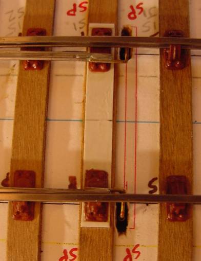
The functional items are by Exactoscale and are used wherever two separate pieces of rail need joining or where an insulating join is needed. This enlargement (left) shows the "H" shape of the one-piece ABS-plastic moulding. Note where the plastic from the chair has been drawn into the grain of the sleeper by the solvent.
The cosmetic variety are by C&L Finescale and are positioned wherever required by the prototype
 In the past I experienced problems with these fishplates, which were simply glued to the side of the rails, coming adrift. Whether this was due to the two materials expanding and contracting at different rates as the temperature changed, or insufficient degreasing of the railside I not know but now, after cutting a cosmetic break in the head and foot of the rail, a pair of 1mm diameter holes is drilled through the web.
 Remove the triangular nib from the backs of the C&L mouldings and use solvent to attach one half to the rail. Poke a couple of lengths of 0.75mm (30thou) plastic rod though the holes and glue to the fishplate. Leave overnight to set, then remove the excess rod and attach the other half of the fishplate. Remember that the rounded bolt-heads go on the inside and the square nuts on the outside.
Cruelly enlarged, the obvious faults shown in these pictures are virtually invisible when viewed in reality e.g. cosmetic rail-break not in centre of fishplate; significant difference in gap size between the cosmetic and functional fishplates. To give you some idea of the enlargement the rail is only 3.2mm (one-eighth of an inch) high. Some representation of the ends of the bolts protruding through the nuts would be nice next time the mould tools are refurbished...